Technical Features :
Manufacturing Standards
IS-2026 / IEC-76
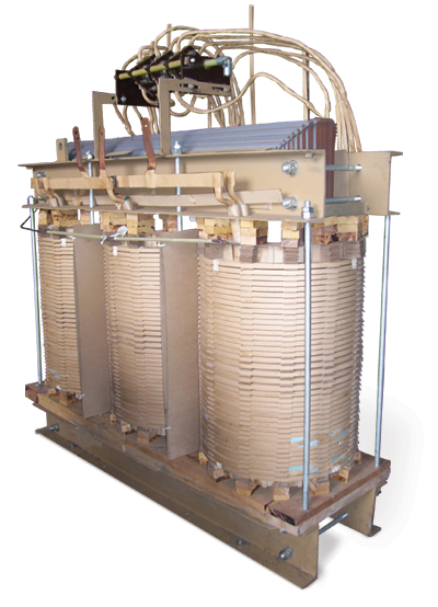
Core
The Core is build up from interleaved low loss cold rolled, grain oriented Silicon Steel laminations. Individual stampings are coated on both sides with an insulating material, which is both oil and temperature resistant. The core limbs are securely bound with heavy duty webbed cotton taps and the yokes are firmly clamped between steel channels, all cores have mitered joints. Top and bottom clamps are secured to each other by means of tie rods which serve the dual purpose of securing the windings in place and of transferring the load from the bottom to the top clamps when the core and windings are lifted. This prevents tensile stresses being set up in the core legs which could adversely affect the iron losses.
Windings
Transformer windings are designed to meet three fundamental requirements such as mechanical, thermal and electrical. They are cylindrical in shape and are assembled concentrically. The low-tension windings are of the helical type, single or multilayer, using flat copper strips, depending upon the size and current rating of the transformer. The high-tension windings consist of paper covered conductors (round and strips) depending upon the current rating of the transformer. For higher capacity continuous disc windings are used. The windings are rigidly supported by pressboard washers and spacers. Interlayer cooling ducts are provided to ensure that the temperature gradient between windings and oil and hence the hot spot temperature is minimized and higher life expectancy is achieved. Insulation between layers and turns is based upon the impulse test level of the voltage class of the windings as specified in IS 2026.
Completed Core coil assemblies are dried prior to impregnation with transformer oil.
Winding Connections
Tappings and leads are run in multi paper covered flexible conductors in press board half tubes, the phase leads being separated from the tapping leads by adequate barriers. These tubes are rigidly based to ensure that clearances between leads and tank sidewall are maintained when the transformer is fixed in position. Low voltage leads being of larger cross section are sufficiently robust, so supports are provided wherever necessary.
Insulation and Impregnation
The principal components of insulation are pre-fabricated from pressboard sheet. All items subjected to compression in services are preshrunk and the slight recovery in dimensions after preshrink age is compensated for windings during final drying of the completed transformer. The oil used for impregnation complies with IS 335 and every consignment received at works is tested before entry is permitted into the storage tanks.
Short Circuit Strength
In order to prevent deformation when subject to short circuit force, solid blocks and insulation, backed by substantial supporting frames, are utilized. The axial end thrust under fault condition is minimized by ensuring that design dimensions are closely adhered during manufacturing procedure. Transformers are designed and constructed in such a way that they are capable of withstanding the effect of short circuit testing. Our transformers have been type tested at CPRI and ERDA.
Tapings
For the range of transformer covered in this Catalogue, tapings are provided on the H. T. Windings at ±5% in steps of ±2.5%. Other tapping ranges can be supplied on request. Tap selection is effected by means of an off-circuit tapping switch operated by an external handle. Leads for Tapings are brought away from the coils by the means of paper insulated conductors. They are arranged in such a manner that the ampere-turn balance is maintained throughout the tapping range. ON-LOAD TAP CHANGRES are also provided depending upon customer requirement.
Terminations
All bushings are of high quality porcelain or Epoxy complying as per IS 2099
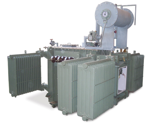
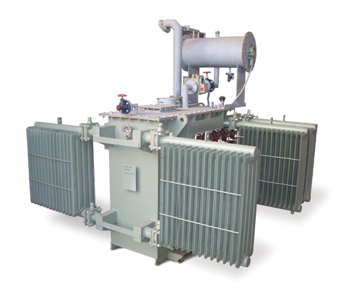
Oil Cooled Transformer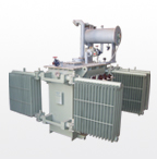
Oil Cooled Transformer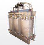
Oil Cooled Transformer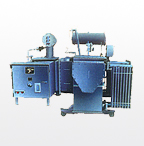
1000 KVA With OLTC